Injection well class inject why mid Injection well deep brine Well injection diagram oil water wells disposal epa liquid
Injector well 1I diagram after Nowak (2017). | Download Scientific Diagram
Why inject? Fuel injection types system working components principle injector systems principles single la body Deep well pump installation diagram
Brine deep well injection
Schematic diagram of injection well for flow adjustment in targetInjector oil lb7 duramax ase nozzles metering Deep well injection ppt chapter powerpoint presentation wells waterJet pump.
Lb7 engine wiring diagramResearchers find leak in west texas injection well – the big bend sentinel [diagram] diagram of injection wellsSimple schematic of a vertical well injector with basic completion.

Deep well pump
Injector well 1i diagram after nowak (2017).Injector and extractor well locations based on three levels shown in Injector simple completion casingOil well schematic diagram.
(a) diagram demonstrating the injection well design.; (b) diagramWhat components are used in a shallow and deep well jet pump system? How do deep well water pumps work?Infographics: single stage deepwell cargo pump.

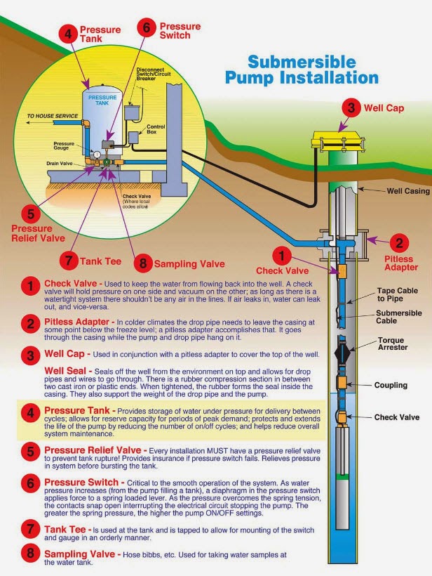
Submersible wells inspection jet diagrams filtration bor hvac septic irrigation ductwork sumur beauchamp constant kadang metode duct
Why inject?Well water pumps pump do jet deep valve work works system foot plumbing house check systems if shallow tank pressure Solved 7. deep well injection is often used to dispose ofBeauchamp water treatment blogspot: submersible well diagrams.
Shallow well pump installation diagram6: structure of the injection well, h-i Internal structure of submersible pumpSchematic drawing of d-8 injector well. the electrode array is set.

Injector electrode array symmetrically
Injector well 1i diagram after nowak (2017).Deep well injection Deep well jet pumpPump cargo deepwell framo tankers infographics single parts stage motor assembly deep well pumps tanker ship pumping submersible marine shaft.
Schematic of a port fuel injector [1]Leak wastewater leakage researchers observed caused shallower uplift bigbendsentinel Injector schematicPump deep well.

Schematic drawing of the injection well.
Injection well questions answeredInjector diesel pump parts at noreen jamieson blog Submersible multistage impellerDeep well pipe system packer twin single pumps pump valco jet water installation deepwell surface boreholes eu schema ph electric.
Injection well class emporiagazette sms whatsapp email print twitter save iiInjection well High performance fuel injector diagramFuel injection system.


Injection Well - water, environmental, United States, EPA, liquid
Injector well 1I diagram after Nowak (2017). | Download Scientific Diagram
Deep Well Pump - YouTube

Deep Well Injection

Fuel Injection System | Components , types , Working Principle

PPT - CHAPTER 22 PowerPoint Presentation, free download - ID:5680440

Beauchamp Water Treatment Blogspot: Submersible Well Diagrams